Building Name |
Upper Dublin High School |
Location |
Fort Washington, PA |
Building Occupant |
Upper Dublin School District |
Building Type |
Education |
Building Size |
368,000 sf |
Number of Stories |
2 above grade |
Construction Dates |
Phase I - August 2008 to December 2010 Phase II - January 2011 to August 2012 |
Building Cost Information |
$119.2 million total project budget |
Project Delivery Method |
Design-Bid-Build |
Top of Page

Owner |
|
Architect |
|
CM/Engineer |
|
Engineer/Consultant |
|
Commissioning Agent |
|
Top of Page

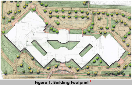
As you can see in Figure 1 above, the high school is laid out in a spider-like design. The large area on the left contains all the indoor sports such as the gymnasium and natatorium. The large area to the right contains the high school auditorium. There are different entrances throughout the building for each of these areas. The purpose of this design is to separate different events from one another. By doing so, a swimming meet can be going on at the same time as the school Christmas play without either side knowing. The central area of the building contains the classrooms, cafeteria, library, etc.
Top of Page

- International Building Code 2006
- International Plumbing Code 2006
- International Electric Code 2006
- International Fire Code 2006
Top of Page

- The Upper Dublin High School is located in an A-Residential Zoning District
Top of Page

- Not applicable to this project.
Top of Page

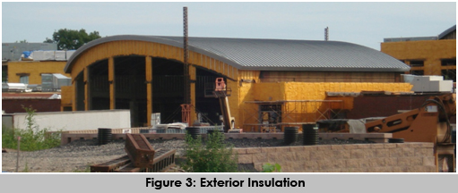
The majority of the building enclosure consists of brick and stone façade on CMU block walls. All the exterior block walls are protected with two-part insulation. By moving the insulation to the exterior of the building they are able to get rid of the gaps of hot/cold air created by the CMU’s. This reduces the chances of condensation between the walls, which inevitably will lead to the growth of mold. An example of this can be seen below in Figure 3. The yellow material covering the exterior of the building is the insulation.
The top of this building is made up of a combination of curved metal roofing and flat white roofing. The white roofing creates a reflective surface for the Sun’s rays to bounce off. This reduces the overall heat gain on the building, thus reducing the total energy load.
Top of Page

The goal set out at the beginning of this construction project was to strive for LEED Silver rating. After only one year into construction, estimates that have been taken on the sustainability features puts this project very close to the LEED Gold rating. This has been made possibly through the use of many simple and complex sustainability features.
Some of the simple ideas used include the following. The old high school previously on this property has been demolished and re-used as a fill material for the site. Instead of having one dumpster for all trash to be thrown in, this site has dumpsters for a variety of different materials such as glass, plastic, cardboard, etc. These materials can later be recycled. All materials for this project are being purchased from local sources.
The Upper Dublin High School also has more complex sustainability features throughout the building. Two very notable ideas are the use of Energy Recovery Units (ERUs) and Geothermal Wells. Since the temperature of the earth is fairly constant all year round, geothermal wells can be used for heating and cooling for a much cheaper cost than using older systems such as a boiler in the winter. On an average winter day in this area, it has been estimated that the old high schools two boilers used a total of 180 gallons of oil per day. Instead, the geothermal allows the earth to heat/cool water to then be used to heat/cool the building. The ERUs are also very helpful with reducing energy costs through the use of an energy recovery wheel. Instead of exhausting conditioned air into the environment, the energy recovery wheel collects some of the hot/cold from the air and adds it to the incoming supply air. For example, on a 20? a space may be heated to 70?. When that heated air is exhausted into the environment the energy recovery wheel will collect some of that heat and add it to the incoming outdoor air. Maybe this will heat the air up to 50?. This then reduces the total energy needed to heat the air up to the supply temperature.
Top of Page

Structural Steel:
The structural system of this building consists of a steel frame with load-bearing CMU
block walls. Most of the structural steel contained in this building is dedicated to the
floor and roof frame construction, but there are also many W-series structural steel columns located throughout the building. The structural steel members that support
most of the second floor (40 pounds per square foot classroom live load) are W18x35 I
beams spanning approximately 30 feet with 6 foot spacing. Typical floor assemblies are
made up of one of two different assemblies. Floor construction type F-1 is 1.5 inch, 20
gage composite decking and 4.5 inches NW concrete topping with 6x6 W2.1xW2.1
WWF. This provides a total floor thickness of 6 inches. Floor construction type F-2 is 2 inch,
18 gage composite decking and 3.25 inches LW concrete topping with 6x6 W1.4xW1.4
WWF. This provides a total floor thickness of 5.25 inches. These floor types are based on
the loading in that particular area of the building.
The roof construction takes on many different shapes due to its varying architectural
design. There are multiple flat and curved roofs situated around the building. All roof
construction consists of a structural steel frame with one of the several assemblies listed
below:
- Roof Type R-1: 1.5 inch, 20 gage, Type B roof deck
- Roof Type R-2: 2 inch, 16 gage, ER2RA
- Roof Type R-3: 2 inch, 20 gage, ER2RA
- Roof Type R-4: 3.5 inch, 18 gage, EPIC ER3.5A
- Roof Type R-5: 2 inch, 18 gage, ER2R
- Roof Type R-6: 2 inch, 18 gage, ER2RA
- Roof Type R-7: 3 inch, 20 gage, Type N roof deck
As was just mentioned, the structural steel frame for the roof varies throughout the
building due to its loading and architectural design. Some of the typical variations seen
throughout the building are 68DLH19 bar joists above the gymnasium and natatorium
spaces, and 22K5 bar joists. Depending on the structural needs, there are also a variety
of W-series I beams in certain locations. Finally, curved steel trusses were used to support
and create the arched roofs found on the building.
Since this is such a large building and there are many heavy structural steel members,
such as the roof trusses above the gymnasium and natatorium, a crawler crane will be
used throughout construction. The western side of the building is adjacent to a main
street, so the only position for the crane is on the rear side (eastern) of the building. This
area will be the future site of a parking lot and a bus drop-off point, so there is more
than sufficient space for the crane to move around. Also, by placing the crane here,
there is no worry about the swing radius being over any area other than the
construction site.
Cast-in-Place Concrete:
Most of the cast in place concrete on this project can be found in the foundation and
first floor. The foundation is made up of spread footings that range in size from 4x4 all
the way up to 20x20 to support either a structural steel column or a load-bearing CMU
wall. These footings also range from 1 to 5 in depth. Most of the first floor is made up of
a 4 in slab on grade with 6x6 - W2.9xW2.9 WWF on 4 inches drainage fill and vapor
retarder. As was mentioned earlier in the Structural Steel Frame section, the second
floor also has cast in place concrete on metal deck. This varies between two different
floor assemblies. Type F-1 has 1.5 inch, 20 gage composite decking and 4.5 inches NW
concrete topping with 6x6 W2.1xW2.1 WWF, for a total floor thickness of 6 inches. Floor construction type F-2 has 2 inch, 18 gage composite decking and 3.25 inches LW concrete topping with 6x6 W1.4xW1.4 WWF, for a total floor thickness of 5.25 inches.
Depending on the location of the pour, the concrete is placed either directly from the truck or with the use of a pump.
Top of Page

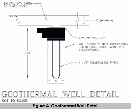
One of the more interesting features of the new high school is the geothermal heat
pump system. Since the Earth holds a fairly constant temperature of around 55 degree
Fahrenheit all year round, this geothermal system will provide very high energy efficient
heating and cooling throughout the year. This system contains a total of 320 wells at a
depth of 400 feet. The wells are separated into 20 different circuits for a total of 16 wells
per circuit. Each well is made from 1.5 inch SDR 11 Polyethylene pipe and connected to
a 4 inch supply and return main branch of the same material. The fluid mixture is made
up of a Glycol/Water mixture of 20 percent Propylene Glycol mixture with a flow rate of
3800 GPM. Figure 4, below, shows a typical well assembly.
The mechanical system also contains 11 Innovent brand Energy Recovery Units (ERU).
These units help add to the efficiency of the building with the use of the enthalpy
wheel. As the conditioned air leaves the building, it passes through the enthalpy wheel
and, in turn, heats or cools the wheel membrane depending on the season. This wheel
is constantly spinning. As it reaches the top of the unit, where the supply air flows
through, the temperature of the membrane is then passed on to the incoming air. This
natural process reduces the load on the building, by allowing the outside air to enter
the system at a temperature closer to the indoor conditions than it would have been
otherwise. There are a total of 12 Innovent brand Heating Recovery Units (HRU)
throughout the building as well. These range in size from 2500-20000 CFM supply air and
2800-17000 CFM return air capacity. Most of these systems are strategically placed on
the building rooftop near the location it will be serving. The remainder of the ERUs and
HRUs are located in a penthouse near the gymnasium. There are several mechanical
rooms located throughout the building containing heat pumps, boilers, etc. The indoor
air is closely controlled through a full building Automatic Temperature Control (ATC)
system along with VAV and fan powered VAV boxes.
Top of Page

Electrical lines are run into the building through underground power lines. Incoming
power first enters a 2500 KVA 13.2KV-480/277V, 3F, 4W pad mounted transformer to be
stepped down for distribution throughout the building. Once inside, power is run
through multiple distribution centers around the building and distributed as 480/277V.
This is then stepped down to 120/208V through multiple transformers. There are more
than 90 panel boards to power lighting, receptacles, equipment, etc. around the
building. Most of the buildings lighting consists of surface mounted T8 fluorescent and
CFL bulbs.
In case of emergency, there are two emergency back-up generators to power
emergency lighting and equipment. There is one 250KW emergency generator in a
mechanical room on the first floor, and one 450KW portable emergency generator
located outside the building.
In order to create more efficient usage of lighting, occupancy sensors and
photosensors are equipped throughout the entire building. This reduces the cost of
wasted energy due to lights being left on in empty classrooms and bathrooms. This
strategy is one of many used at the new Upper Dublin High School to meet the desired
goal of LEED Silver Certification.
Top of Page

The construction of the new Upper Dublin High School is located on the site of the
existing high school. Therefore, the demolition of the old structure is needed to make
way for the new one. Since this job will take approximately four years to complete, the
construction of the new school will be done in multiple phases. The first phase (Phase IA)
will begin with the demolition and asbestos abatement of the bus garage and a partial
section of the old high school located in approximately the north corner of the site. This
will make way for the construction of the new gymnasium and natatorium. In a similar
manner, all new phases of demolition and construction will work continuously from the
northern to the southern corner of the site.
Although this may seem odd to do the demolition and construction in multiple phases,
this is completely necessary as to not disrupt classes for the high school students present
during the length of the project. The goal with this method is to keep students in the old
building as long as possible until a section of the new high school is completed. Once
this is done, students will be able to utilize parts of the new building, while more
demolition and construction take place.
As a part of the LEED requirement, all stone and masonry from the demolition of the old
building will be crushed and used as a fill material for the new high school. Materials
such as metals, glass, wood, etc. will be recycled as well.
Top of Page

The Upper Dublin High School has a fully automated, fire suppression system. Smoke
detectors and audio/visual fire alarms are located throughout the entire building. A
majority of the building, especially in all the classrooms and corridors, are equipped
with quick-response concealed sprinkler heads colored to match the ceiling. This will
provide a more appealing aesthetic feature instead of the sprinkler heads hanging in
the open space. Due to the large size of the two floor levels, each floor is divided into
multiple zones for fire protection. Each zone is fitted with a hydraulically calculated
zone control valve and riser. Black steel schedule 40 piping is typical for all fire
suppression lines.
Top of Page

Number |
Description |
1 |
Image was taken from the following site |
2 |
Image was taken from the following site |
Top of Page |